Welcome to the first part of a two-part blog brought to you by the Punch Through Team! We hope this two-parter helps educate readers on a topic at which Punch Through excels. This blog post aims to help you better understand what harmonics are, where they come from, how they relate to Bluetooth Low Energy (BLE), and how to make them go away so you can get back to dreaming about rainbows and unicorns while your product is making you $dough$. Identifying future challenges and knowing where to get help is a critical path to success, and Punch Through is here to help!
Here’s an overview of the topics that will be covered in each post of the two-part series:
Harmonics Part 1 (this part) — Introduction to Harmonics & BLE
- What are spurious harmonic emissions and why can they be bad? Back to the basics
Harmonics Part 2 — Determining the Source of the Harmonic
- How are harmonics generated and how can they be mitigated? A little more technical
This blog post is calling your name if:
- You’ve heard the term “harmonic”, “spurious” or “emissions” thrown around in the electronics industry and are wondering what that’s about.
- Harmonic emissions have ever given you nightmares at some point for a BLE product you were developing.
- You’ve never heard of any of these in your life and are just knowledge hungry — don’t worry, we’ll cover the basics of harmonics and BLE so you’ll walk away satiated.
Let’s get started!
What is an EM field?
Bluetooth devices among other electronics utilizing technologies such as Wi-Fi, cellular, and GPS all communicate wirelessly. These devices all achieve wireless communication by exploiting the electromagnetic (EM) radiation properties of electrical conductors described by good ol’ James Clerk Maxwell:

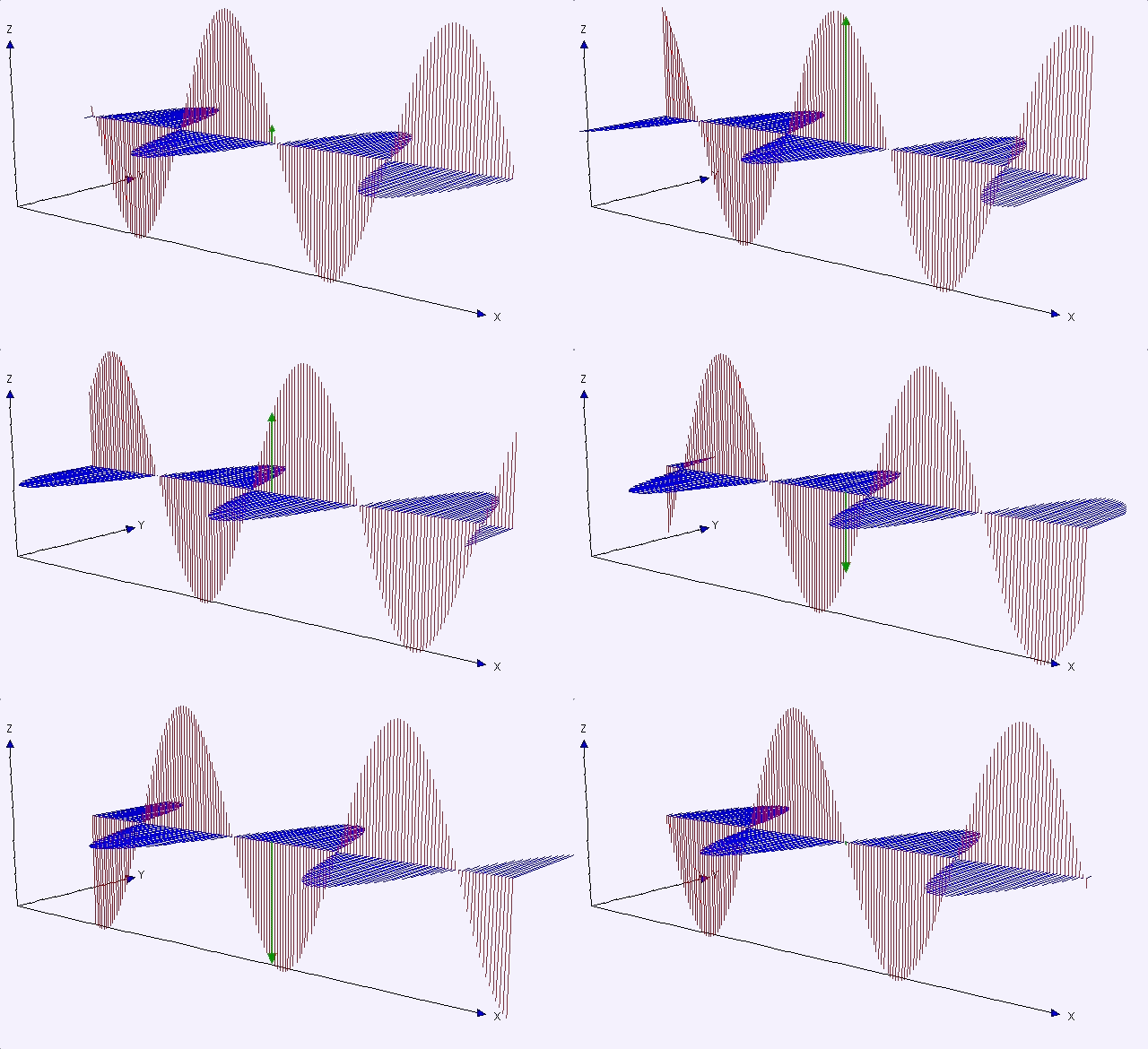
When an electric charge is applied to a conductor such as a wire and current flows through the conductor, it always generates an electric field and a magnetic field. When these two fields are combined they are referred to as an EM field. An EM field propagates through space in the form of waves just like light. In fact, visible light is just another class of an EM wave, which is just a small portion of the entire EM spectrum. The spectrum consists of all EM fields across all wavelengths — visible light wavelengths are much shorter than radio waves (on the order of 10,000 times shorter than your common 2.4 GHz telecommunications wavelength). The wavy diagrams in Figures 2 and 3 depict an EM field moving through space:
At risk of sending you down the deep dark rabbit hole of trying to wrap your brain around quantum physics, it should be mentioned that the EM field traverses through space in the form of photons. Photons are zero-charge, zero-mass particles that move at the speed of light. Any more beyond that and brains turn to mush, so let’s leave it at that.
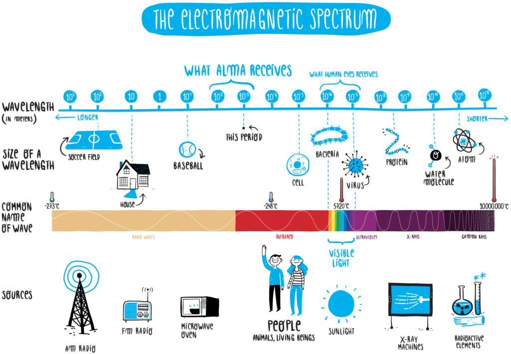
Other examples of EM waves which you may have heard of but can’t see with your eyes are X-rays, ultraviolet, infrared, and also last but not least: the aforementioned “radio waves”. Check out the breakdown in Figure 4 of the EM spectrum by wavelengths, frequencies, and common names of the wave groups. Note that frequency is inversely proportional to the wavelength:
- λ [wavelength] = c [speed of light] / ƒ [frequency]
[Image courtesy of ALMA Observatory]
Various radio technologies typically operate at different radio frequencies (RF) — Bluetooth operates at 2.4 GHz (gigahertz), Wi-Fi at either 2.4 or 5 GHz, GPS is typically 1575.42 MHz (megahertz), and cellular devices can operate at many different frequencies in the range of 700 MHz to 2.6 GHz depending on your region, cell phone carrier, and device support.
For purposes of this discussion, from here on in we will focus on Bluetooth Low Energy (BLE) radios and their operational frequency of 2.4 GHz or wavelength of approximately 5 inches.
How ’bout a spurious emission?
The radio wave part of the EM spectrum is valuable. Valuable enough to a point where government bodies tightly regulate its use. The Federal Communications Commission (FCC) is the United States’ version of this type of regulatory bouncer. If you are using a part of the EM spectrum (deliberately or inadvertently) to a point where it merits an investigation by them, they will find you and they will shut you down. They have chopped up radio wave EM spectrum into many sections, some of which are more loosely regulated than others. One of the more loosely regulated spectrum sections is at 2.4 GHz. This is why many wireless consumer electronics operate at 2.4 GHz: BLE devices, Wi-Fi routers, garage door opener, even your home’s ancient cordless phone.
BLE radios operate at 2.4 GHz — or more specifically — somewhere between 2.402 GHz and 2.480 GHz at any given time. This frequency range is divided into 40 “channels” in the case of BLE. In the case of Wi-Fi, which can operate in the same frequency range, it is divided into only three “wider” channels. Figure 5 shows a very common and useful depiction of the frequency breakdown of BLE and Wi-Fi. The frequencies of the BLE advertisement channels were specifically designed to exist between the three Wi-Fi channels. When two BLE devices are in a wireless connection with one another, they continuously “hop” between the remaining 37 channels while they talk to each other. This channel hopping helps avoid interference caused by a nearby Wi-Fi device using one of the three wider channels or from other nearby BLE devices.
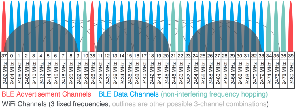
At this point we’ve established that BLE devices deliberately create EM radiation at any frequency between 2.402 GHz and 2.480 GHz and the FCC doesn’t want BLE devices creating EM radiation anywhere outside of that frequency range.
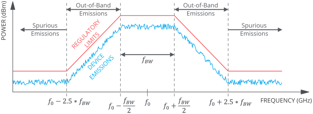
A spurious emission is classified as any EM radiation at a frequency that is not deliberately radiated — particularly in the context of electronics that deliberately radiate one or more frequencies. The FCC requires all electronics to undergo testing to ensure they do not radiate EM waves of excessive intensity across all frequencies other than those that are deliberately radiated — this is known as electromagnetic compatibility (EMC) testing. Figure 6 depicts such a test for a wireless device operating at a given frequency and bandwidth. The start/stop frequencies of the domains labeled out-of-band (OoB) emissions are a function of the signal’s bandwidth. The domains labeled spurious emissions extend continuously past the edges of the image. For example, if the signal’s bandwidth is ƒBW, then in typical cases the OoB emissions domain will start at ƒ0 +/- 0.5*ƒBW and the spurious emissions domain will start at ƒ0 +/- 2.5*ƒBW . If the power level in any of those domains is above the domain’s power limit, your device will fail the test and will need to be fixed before it can be used.
And a harmonic spurious emission?
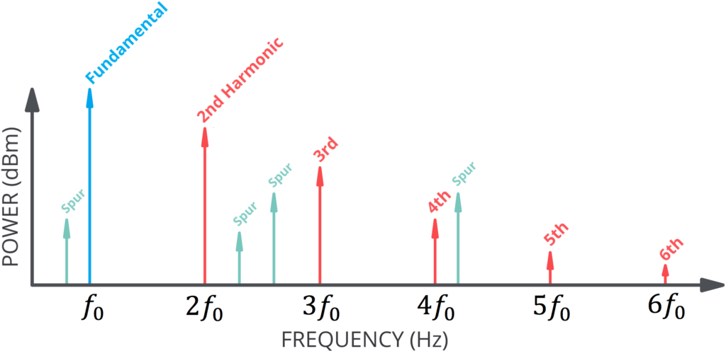
Spurious emissions are just any EM radiation that is generated by an electronic device when the electronic device is not intentionally generating the EM radiation. A harmonic spurious emission is just a special type of spurious emission. In the regulatory certification context — such as the FCC — it typically applies to wireless electronics that deliberately generate EM radiation at one or more frequencies. A harmonic is just any integer multiple of a single frequency — this single frequency is usually referred to as the fundamental frequency or sometimes the first harmonic. So your fundamental frequency (ƒ0 ) harmonics would be:
- 1st harmonic = 1 x ƒ0 = fundamental frequency
- 2nd harmonic = 2 x ƒ0
- nth harmonic = n x ƒ0
In a frequency vs. power plot, a fundamental frequency of ƒ0 with harmonics up to the 6th harmonic would look something like what is shown in Figure 7. Notice there are other non-harmonic spurious emissions included as well, but these could very well be harmonics showing up from some other fundamental frequency.
But, why are spurious emissions bad?
Let’s start out by stating that not all spurious emissions are “bad”. Sometimes the fundamental frequency is actually an intentionally created harmonic of some lower frequency. These “tricks” are commonly used in RF design.
However, in the context of unwanted spurious emissions, they are bad. These spurious emissions always exist but they may not always be a major PITA.
In the FCC’s eyes, they don’t want an electronic product unnecessarily crowding the EM spectrum with unintentionally created EM radiation. If an electronic product generates too much EM radiation at some unintentional frequency, it may wirelessly impact or interfere with another electronic product intentionally using that same frequency. The FCC has set specific limits across all frequencies of the spectrum to avoid this type of interference and pollution of the EM spectrum. An RF jammer device (which is illegal in the United States) is an example of an electronic device that maliciously exploits EM interference by generating severe levels of EM radiation at either a specific frequency or a wide range of frequencies to degrade the performance of nearby wireless electronics.
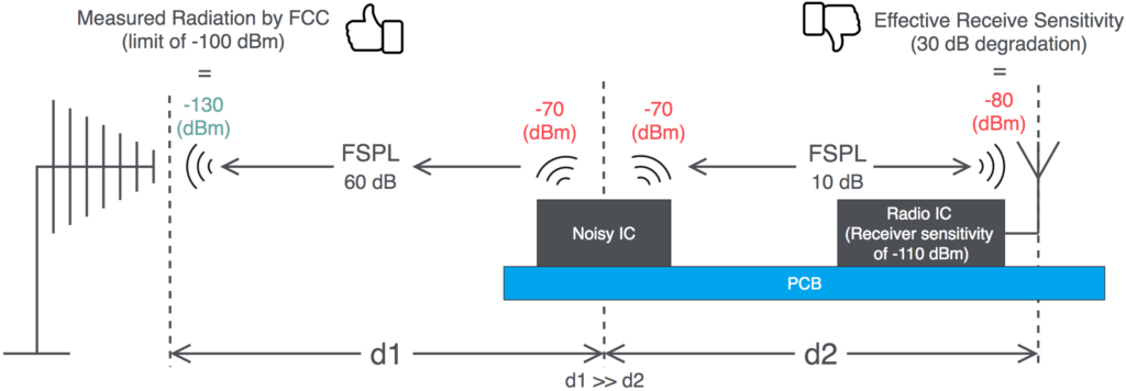
In the wireless electronic designer’s eyes, spurious emissions can cause headaches other than not passing regulatory testing — figuratively speaking of course, unless they stress you out enough. Sometimes, the spurious emissions generated by a wireless electronic aren’t severe enough to be above the limits set by the FCC, but they still exist. And if they exist at the right frequency, the right time, and the right intensity they can start to “drown out” the electronic’s receiver, effectively making it less sensitive to low signal levels. This is essentially the same effect a jamming device has on a poor defenseless radio victim and is commonly referred to as “receiver defense”, “self-jamming”, “self-interference” or “self-quieting” (maybe most appropriately compared to shooting yourself in the foot). Figure 8 diagrams this self-quieting scenario. Without going into much detail, free-space path loss (FSPL) is just how much power is lost between signal source and signal receiver due to the distance the signal travels through the air; as distance increases, the power loss increases. The sideways Christmas tree-looking thing on the far left is the emissions “test” antenna and the radio electronic’s “device” antenna is shown on the far right. The “noisy IC” emits unwanted emissions at a power level of -70 dBm. The noisy IC is much closer to the device antenna than the test antenna, thus the -70 dBm emissions from the noisy IC is attenuated by air by only 10 dB versus 60 dB attenuation towards the farther away test antenna. The noise power level received by the test antenna is then -70 dBm minus 60 dB = -130 dBm, which is less than the FCC’s emission limit of -100 dBm, so the electronic passes the FCC’s emission test. The noise power level as received by the device antenna is -70 dBm minus 10 dB = -80 dBm. This is bad for the radio’s receiver because under ideal conditions it is capable of detecting communication signals down to a very small -110 dBm power level. However, because the radio is receiving -80 dBm of noise, it can no longer detect any communication signal less than -80 dBm. Otherwise said, the radio’s receiver sensitivity of -110 dBm is inhibited by 30 dB and now has an effective receiver sensitivity of -80 dBm.
Unintentional radiator vs. intentional radiator
As mentioned previously, a spurious emission is just EM radiation that is not deliberately created by an electronic device — particularly by electronics that “intentionally radiate” specific frequencies. Most of today’s electronic devices fall under one of the following categories defined by the FCC: “unintentional radiators” and “intentional radiators.” Intentional radiators are the electronic devices mentioned that deliberately radiate specific frequencies, such as BLE devices. Conversely, unintentional radiators are “all” other electronic devices that do not intentionally generate EM energy for wireless communication purposes. Of course, there are exceptions where an electronic doesn’t fall into one of these two categories or it is exempt from rules set forth for devices in these categories, but we’ll ignore those for this discussion.
The FCC requires that “all” electronics undergo testing defined for the unintentional radiator category. The main test for electronics that fall into this category measures for spurious emissions in the 30 MHz to 1000 MHz range. These tests usually include several pieces of special (i.e., expensive) equipment to measure emissions from the electronic device or Equipment Under Test (EUT):
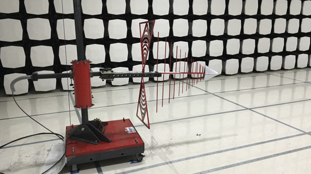
- Test antenna (log-periodic or horn) to receive the spurious emissions emanating from the Electronic Under Test (EUT) — this test antenna is typically placed either 3 meters or 10 meters from the EUT:
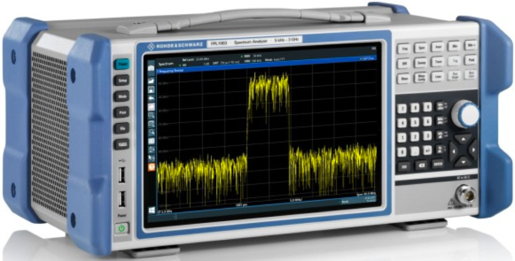
- Spectrum Analyzer to measure the power of the spurious emissions picked up by the test antenna:
[Image courtesy of Rohde & Schwarz]
- Low Noise Amplifier (LNA) to amplify weak RF energy picked up by the test antenna so the Spectrum Analyzer can actually detect the RF energy emanated from the EUT:
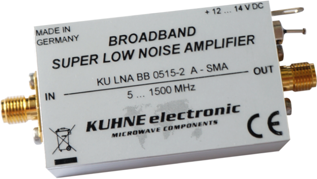
[Image courtesy of Kuhne electronic]
- Large RF anechoic room isolated from external radio waves — essentially a room with metal ceiling, walls, and floor with material on the walls that absorbs RF energy. This room could potentially be replaced by a large open field out in the countryside (far away from any RF energy sources such as cell phone towers and consumer electronics).
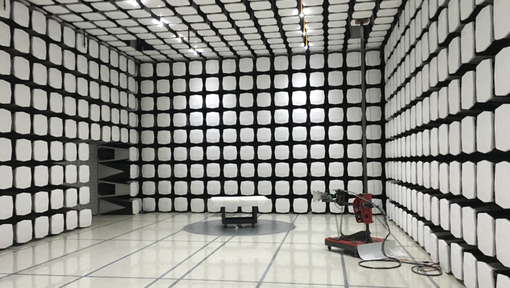
During these tests, the emissions from the EUT need to be measured from all angles in a single plane. Otherwise said, the emissions should be measured while the EUT is slowly rotated 360˚. This is typically done by placing the EUT on a turntable that rotates slowly. Alternatively, you could manually do this by taking a measurement, rotate the EUT slightly by hand, take another measurement, and repeat until all 360˚ have been measured. Not ideal. Then, while still having the test antenna pointed at the EUT, rotate the antenna 90˚ and start the 360˚ EUT rotation all over again. http://i.imgur.com/RGz3IET.gifv
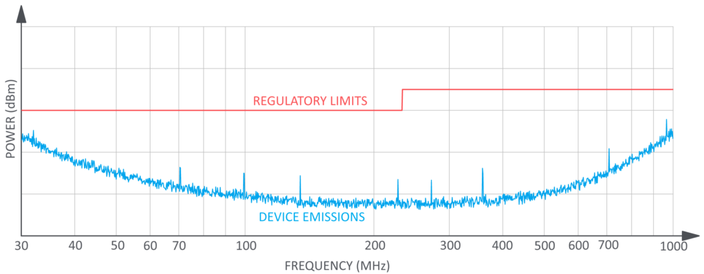
The EUT should be continually operating in an active state while this test is scanning for unintentional emissions; if the electronic contains a radio that can intentionally generate EM radiation, it should be set in a “receive only” mode where it does not transmit EM energy. Sometimes, the power level of spurious emissions vs. frequency looks pretty “quiet” and boring like the plot shown in Figure 13. When this happens, the underlying trend line of the trace is the “noise floor” of the measurement equipment — background noise. Even with no EUT in the test chamber, the test equipment would measure this noise floor.
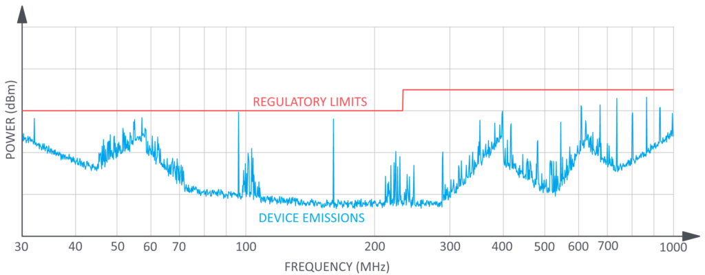
Although often times, even when designs are made with special attention given to controlling EM radiation, it looks 2spooky4me like this but is still passing FCC limits:
In addition to the unintentional radiator emissions tests, the FCC requires intentional radiator electronics to undergo further testing defined specifically for their intended frequency of operation. The main test we’re concerned with in this discussion is the intentional radiator spurious emissions scan while the EUT is continuously radiating RF power at its intended transmission frequency.
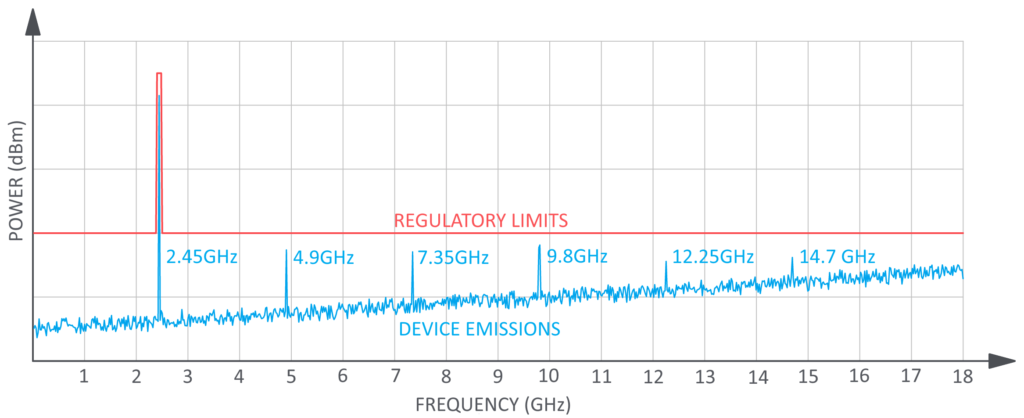
In the case of BLE — which can transmit on any of 40 channels from 2.402 GHz to 2.480 GHz — the FCC requires the intentional spurious emissions scan be run three separate times while your device is set to continuously transmit on the lowest frequency channel (2.402 GHz), the middle frequency channel (2.440 GHz), and the highest frequency channel (2.480 GHz). The most common failure in this test is due to harmonic spurious emissions that were mentioned earlier (the 2nd, 3rd, …nth harmonics of the fundamental 2.4 GHz transmission) being too high. Figure 15 shows what a common test scan (passing FCC limits) may look like. Notice that the fundamental frequency of 2.44 GHz is above the spurious emission limit line, which is just fine because the limit doesn’t apply to the fundamental frequency. The 2nd and 3rd harmonics show up at 4.88 GHz and 7.32 GHz but are below acceptable limits.
Until next time…
The whole EMC testing process required by the FCC (and regulatory agencies in countries other than the USA) can be very cumbersome to people going through it their first few times, even if their product passes all the tests with flying colors. Punch Through is here to help at any stage in the process! We have successfully enabled many of our customers to start shipping their product by helping them fix arduous EMC issues — more on that to come in the second part of this blog post!
Continue on with Harmonics Part 2 – Determining the Source of the Harmonic!

