
Bluetooth Low Energy (BLE) is a wireless communication protocol. As with other communication protocols, BLE uses a layered design, where each layer is associated with a specific aspect of the protocol. Interlayer interaction is restricted and well-defined, and this compartmentalization provides several benefits, including abstraction.
Abstraction lowers the barrier of entry for developers looking to build applications on top of a protocol. For example, a developer looking to create an application on top of BLE only really needs to understand the upper layers of the stack (GAP, GATT) to begin application development. That being said, a better understanding of all layers of the stack allows a developer to take advantage of all the tools that the protocol has to offer. Achieving this can be challenging, especially as you delve further into the stack, peeling away the layers and getting into the nitty-gritty details of the protocol.
With BLE, as with any communication protocol, the ultimate foundation lies in the physical layer, the specifics governing the transportation medium. If you’re anything like me, understanding this can seem a bit daunting at first. However, further understanding is worthwhile and lucky for you, Punch Through is here to help.
Set your worries aside and read on to learn about Bluetooth PHY and how you can leverage it for your application.
What is PHY and How Does it Relate to Bluetooth Low Energy?
PHY is short for Physical, as in the Physical Layer. This is the bottom layer of the BLE stack and is responsible for actually transmitting and receiving information over the air via radio waves.
BLE, in particular, transmits on the 2.4GHz band, also known as the Industrial, Scientific, and Medical (ISM) band. There are a number of advantages to transmitting on this band. Mainly, it is a license-free band that is essentially free to use for short-range applications. It’s also the only license-free band that’s the same in every country. Unfortunately, these benefits make the 2.4GHz band a popular choice, and as a result, overcrowding and congestion are common issues.
How Information Is Actually Sent
In general, information can be coded into radio transmissions via a number of schemes, such as varying the amplitude, phase, or frequency of a wave. For BLE specifically, information is transmitted using a scheme called Gaussian Frequency-Shift Keying (GFSK). This is a refinement of Frequency Shift Keying (FSK), where information is coded by shifting the frequency up and down.
Each one of these shifts creates what is known as a ‘symbol’ in the transmission, and encodes a distinct piece of information. It’s easy to assume that symbols and bits are synonymous, but that isn’t necessarily the case. Based on the modulation scheme, multiple symbols may be used to represent a single bit, or a single symbol could potentially represent multiple bits.
With BLE modulation specifically, a zero is coded to negative frequency deviation of at least 185kHz, and a 1 is coded to a positive frequency deviation of at least the same amount. At just the physical layer, BLE is capable of transmitting 1 million symbols per second. This translates to 1 Mbps assuming an encoding of 1 bit per symbol (which is standard for BLE). This threshold in the symbol rate is due to a limitation caused by intersymbol interference. Also, this is an idealized value that doesn’t take into account factors such as packet overhead.
Factors that Influence Range
Now that we understand how the foundation of the physical layer translates to bit rate, let’s shift our attention. The range is ultimately determined by the maximum distance at which the receiver can decode the transmission within a certain accuracy threshold, known as the Bit Error Rate (BER). For BLE, this is set at 0.1% BER.
There are a number of factors influencing the possible range within this BER. Requirements for receiver sensitivity, transmit power, radio tolerance and drift, all help to enforce a minimum range for BLE devices. Furthermore, BLE operates across 40 channels, each spaced 2MHz apart, allowing for robust communication even in crowded environments. When considering maximum range, the main issue at hand is Path Loss, that is how much power is lost from the transmission traveling from the transmitter to the receiver. The lower the power of the signal at the receiver, the lower the signal to noise ratio, and conversely the higher the bit error rate.
Bluetooth PHY and the Arrival of 5.0
Up until this point in the article, Bluetooth PHY has been referred to as a singular configuration. This was, in fact, the case up until the release of Bluetooth 5.0 details multiple Bluetooth PHY configurations that provide various tradeoffs in terms of range and throughput.
What is 1M PHY?
1 Megabit PHY, commonly referred to as 1M PHY, has been the de facto Bluetooth PHY up to this point. The name refers to the bit rate that this PHY is capable of. This is the PHY that was discussed in detail in the previous section. Support for this PHY is mandatory to maintain backward compatibility with all non-5.0 devices
What is Coded PHY?
Coded PHY is a new PHY configuration introduced in 5.0. The purpose of this configuration is to increase the maximum range without increasing transmit power. This sounds contradictory at first glance, but it makes more sense when framed in terms of the BER. Namely, increased range can be thought of as a side effect of reduced error rate. Coded PHY provides enhanced bit error detection and correction, allowing further range while staying within the maximum BER. This is achieved at a cost to data rate, as it increases the number of symbols per bit (with possible values of either 2 or 8). The specifics of this merit further discussion, but unfortunately they’re beyond the scope of this article. See “Exploring Bluetooth 5 – Going the Distance” from the Bluetooth Blog for further information.
What is 2M PHY?
2 Megabit PHY (aka 2M PHY) is also a new PHY configuration introduced in 5.0. The purpose of this configuration is increased symbol rate at the PHY layer. Specifically, it achieves a symbol rate of 2 Mega symbols per second, where each symbol corresponds to a single bit. This allows a user to double the number of bits sent over the air during a given period, or conversely reduce energy consumption for a given amount of data by halving the necessary transmit time.
Technically speaking, this is still almost identical to 1M PHY, with the main difference being an increased frequency deviation to counter the increased intersymbol interference caused by the double symbol rate. A frequency deviation of at least 370 kHz is required as opposed to 185 kHz. The tradeoff here is that the higher symbol rate means potentially higher bit error rate, which means a reduced range (about 80% of 1MB PHY). Support for Coded and 2M PHY only exists within 5.0, and even then support is optional.
Setting the PHY
Though the focus of this article is how the PHY works, it’s worth mentioning the procedure for negotiating the PHY. The PHY is set after a connection by examining the capabilities and configuration for both devices in a procedure that is known as the PHY Update Procedure. While either the master or the slave can initiate this procedure, the master gets the final say. For more information see the Bluetooth Spec Version 5.0, Vol 6, Part B, Section 5.1.10.
It’s interesting to note that this implies the ability to set the PHY of the device on the fly. This opens the door to the possibility of dynamically selecting the PHY that best suits the current need assuming support from both devices. Great in theory, but the degree of benefit this provides in practice remains to be seen.
2M PHY and Application Throughput
At this point you may be wondering “2 Mb is great on paper, but will this double my application data rate?” This is a valid question, and the answer is “it depends”.
As mentioned previously, the PHY is at the bottom of the stack, and application data needs to traverse the entire stack before it gets sent over the air. The point being, there are a number of other factors influencing the application data rate outside of the physical data rate. Let’s examine some of these and discuss how they interact with the PHY. This should allow you to make some comparisons between 2M PHY and 1M PHY as it relates to the parameters of your application, so you can decide whether supporting 2M PHY is worthwhile for you.
The data discussed in this section and referenced in the tables below is from the Nordic S140 softdevice specification [1]. Its original intent is to outline achievable throughput with the Nordic softdevice, meaning that the results are theoretical maximums in ideal conditions for two NRF52s. Introduction of a mobile device may present other variables that limit these maximums. Even so, the data provided is still useful for outlining the various factors affecting throughput with 2MB PHY.
Table 1 below shows data throughput for a single connection with a connection interval of 7.5 ms. Looking at this table, it’s clear that there are a number of factors that impact throughput.
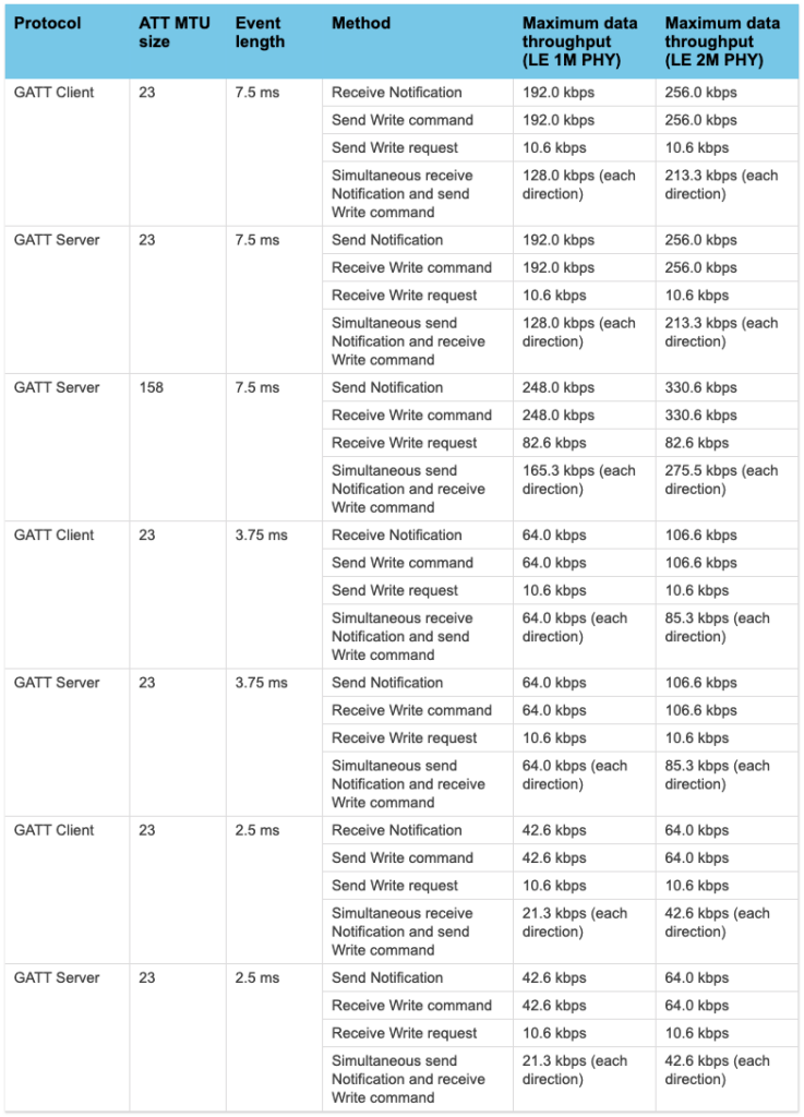
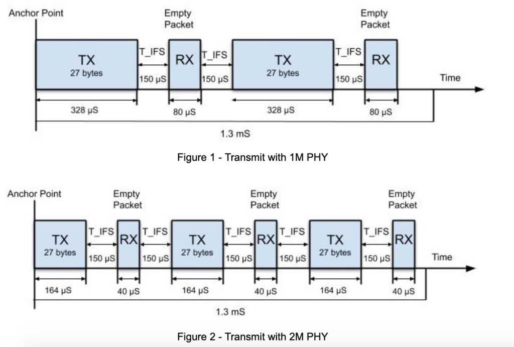
Looking at the improvements from 1M PHY to 2M PHY, throughput is only increased by 33% across the board — even though our physical transmit rate is doubled. Why is this? Because even though our transmit time is cut in half, interframe spacing remains constant, leading to increased time devoted to interframe spacing. This concept is visualized in Figures 1 and 2 below.
Though the example below is simply intended to illustrate this concept, one may notice that the increase doesn’t exactly match the 33% found in the table above. This is because there’s another factor at play: the duration of our connection event length, and how many TX-RX exchanges fit within said event length. Much of this overhead is reduced in duplex communication (as shown in the bottom row of the table), due to elimination of the empty response packets, which in turn reduces the amount of interframe spacing per connection event.
What about write requests (aka write with response)? Why do they have greatly reduced throughput and no difference between PHYs? This is because the underlying assumption with write requests is that the peer response occurs in the next connection event and thus throughput is limited to one ATT PDU every other connection event. While this may negate any throughput gains from 2M PHY, the data rate is still higher, meaning lower power consumption for the same amount of data.
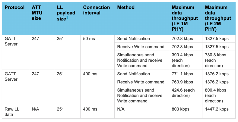
Another feature worth noting is how 2M PHY interacts with data length extensions. As shown below in table 2, we have a LL payload size of 251, meaning data length extensions are enabled. We see a much greater improvement from 1M to 2M PHY, with an overall increase of 90%. This is because the size of DLE packets means a favorable ratio of data to space, even at the doubled symbol rate of 2M PHY. However, even with DLE, and interframe spacing has a measurable impact, keeping our data throughput less than double from 1M PHY.
2MB Bluetooth PHY Increases Throughput, but not Without Downsides
2M PHY is no joke when it comes to increasing throughput. If maximum throughput is your goal, make sure 2M PHY is enabled. Even in applications where no throughput increase is desired, the reduced radio time of 2M PHY still provides valuable power saving.
This doesn’t mean it is not without downsides. Higher transmit rate comes at a cost to the range, and using 2M Bluetooth PHY requires that connected devices also support it. Even though 5.0 was released almost four years ago, 5.0 compatible chipset creation and integration introduces multi-year delays. Furthermore, many pre 5.0 compatible devices are still on the market.
It’s naive to assume that 2M PHY will yield double throughput, and in certain edge cases, throughput improvements may be slim. Even with these caveats in mind, 2M PHY is likely worth supporting, whether or not max throughput is desired, due to increased power efficiency compared to 1M PHY.