Integration is an inevitable challenge in firmware development, occurring the moment hardware, software, or entire systems interact. Yet, teams often take a reactive approach—addressing failures only after they surface in testing or, worse, in the field. This leads to unnecessary costs, delays, and project risks.
A better approach is to design firmware with integration in mind from the start. Beyond meeting product requirements, thoughtful firmware design anticipates mismatches, uncovers failure points early, and improves system reliability. Exhaustive testing isn’t always feasible, but an integration-aware approach builds confidence in real-world performance while preventing late-stage surprises.
At Punch Through, we help companies build connected products with firmware that works reliably in real-world conditions, not just in the lab. With experience spanning medical devices, industrial automation, and other complex systems, we take an integration-first approach that reduces risk, minimizes costly setbacks, and ensures seamless system performance.
What’s In This Article
This article explores how we approach firmware design with integration risks in mind, incorporating techniques that prevent failures before they become roadblocks. Here we’ll cover:
- Common Integration Points – Where integration challenges typically arise in firmware development.
- Understanding the Causes of Integration Failures – A breakdown of the root causes behind common issues.
- Design Techniques to Prevent Integration Failures – Best practices we use to mitigate integration risks and ensure robust firmware design.
By proactively addressing these challenges, teams can avoid the high cost of late-stage failures and build more reliable, scalable, and efficient systems.
If you’re working in the medical device space, we’ve put together a dedicated guide on De-Risking Medical Device Firmware Integration. It explores these principles in the context of strict regulatory requirements, safety considerations, and real-world implementation challenges.
Common Hardware Integration Points
Integration points are critical stages where issues emerge as different components—such as software, hardware, and external systems—are combined and tested. A well-designed system can mitigate failures or shift their discovery to earlier stages, reducing risk and improving development efficiency.
On a typical firmware project, the goal is to identify and address potential failures as early as possible, ideally during Development Integration rather than later stages of testing or deployment.
- Development Integration – The earliest stage, where firmware is continuously built and tested alongside software and hardware teams. Automated continuous integration (CI) helps catch issues early, reducing the risk of defects propagating further. We recognize the importance of making this integration point as effective as possible by employing robust, automated continuous integration testing.
- Board Integration – Where firmware is first tested on actual hardware, uncovering issues related to processor interactions, peripheral initialization, power management, and board-specific behavior. Problems missed here become harder to resolve later.
- System Integration – The point where firmware interacts with the broader system, including operating systems, middleware, and external devices. Undetected issues here can lead to instability, performance bottlenecks, or compatibility failures.
- Manufacturing Integration – The stage where firmware is incorporated into the production process. Issues at this point—such as failed provisioning, programming errors, or factory test failures—can cause costly production halts or high defect rates.
- End-User Integration – The final stage, where firmware is deployed in real-world conditions. Issues found here, such as OTA update failures, unexpected user interactions, or critical bugs, can lead to product recalls, customer dissatisfaction, and reputational damage.
Understanding the Causes of Integration Failures
A flawed mindset is believing that integration failures “just happen.” Even experienced developers may adopt this belief after seeing projects that seemed on track unravel during integration testing. However, integration failures don’t occur randomly—they often stem from decisions made early in the design process.
By identifying and addressing these root causes proactively, teams can reduce costly late-stage issues and ensure a smoother integration process. Let’s explore some of the most common reasons integration failures occur.
Common Causes of Integration Failures
Poor Communication
- Poor Documentation – When design decisions, requirements, and interface specifications are poorly documented, misunderstandings arise. Developers may instead rely on scattered resources like emails or messaging threads, easily leading to misinformed development of features and components. Even small details, such as poor programming or device configuration instructions, can cause confusion and delays when firmware is handed off for testing.
- Poor Coordination – Lack of alignment between teams around critical design decisions can cause friction later. Design choices, such as provisioning methods or interaction flows, may not be agreed upon, leading to costly rework. Furthermore, a lack of coordination between teams can cause overlap or gaps in tasks, with the most severe outcome being unimplemented features discovered in late integration.
- Poor Configuration Management – Poor version control and unclear change management can introduce breaking changes that propagate throughout the system. Teams may unknowingly develop against outdated or mismatched firmware, leading to compatibility issues that surface late in the project.
Fragile Design
- Missing or Ambiguous Requirements – Translating the product requirements into firmware design is a critical step, and one of the easiest ways to introduce latent integration failures. Building out a feature based on ambiguous requirements or missing requirements can easily lead to the wrong implementation.
- Timing and Synchronization Issues – Embedded systems often rely on precise timing and synchronization between components. If timing considerations are overlooked during design, interactions between components can become unreliable, leading to missed events, delayed processing, or unintended race conditions. These issues may only surface when multiple subsystems are integrated, often causing costly and extremely difficult to debug issues.
- Lack of Status Visibility – If a device does not reliably report its internal state, external components attempting to communicate with it may misinterpret its status, leading to unintended behaviors. Missing or incorrect state information can cause failures in higher-level systems that depend on accurate feedback, potentially resulting in stalled processes, repeated failed operations, or even system deadlocks.
- Resource Conflicts – When embedded system components attempt to use shared resources (e.g., memory, CPU time, communication channels) without proper coordination, system-wide instability can occur. Resource contention can lead to dropped messages, delayed execution, or system resets, often emerging only when real-world workloads are introduced during integration.
- Error Handling Gaps – A lack of robust error handling can allow failures to propagate unpredictably throughout a system. If errors aren’t properly detected and handled, components may end up in undefined states, retries may be ineffective, and external devices may be forced to handle failures they weren’t designed for, deteriorating system stability.
- Capability Limitations – Early design choices may not consider real hardware constraints, leading to integration failures when insufficient memory, processing power, or I/O capacity becomes apparent. Assumptions about a device interface may overlook constraints in throughput or protocol support needed for compatibility with external system components.
Late Testing
- Deferring testing for integration – An over reliance on integration testing to verify features can cause latent issues to arise during integration testing that would have otherwise been low cost to resolve earlier in the project.
- Poor Test Capability – Without the right tool and test capability to simulate realistic device interactions, more edge cases are left exposed during development. Lack of test infrastructure, especially for critical system interactions or difficult-to-simulate scenarios, often leads to integration surprises.
Design Techniques to Prevent Integration Failures
Many integration failures stem from decisions made early in the design process. Good design can either prevent these issues entirely or ensure they are discovered early, when they are easier and less costly to address. By applying structured design techniques, teams can minimize assumptions, improve communication, and build firmware that integrates smoothly with other system components.
Requirements Reviews and Tracing
One of the most effective ways to prevent integration failures is to refine product requirements amongst stakeholders and perform requirements tracing exercises. Involving stakeholders in requirements reviews fosters alignment between teams, reducing the likelihood of conflicting assumptions about system behavior.
Tracing product requirements down to the design level, ensures that every requirement maps to specific firmware components, and critical features are not overlooked. Establishing a requirements trace also creates a strong foundation for testing, where implementing requirements traceability from the product requirements to test cases ensures tests thoroughly verify the product requirements.
Lastly, requirements tracing enhances risk management by linking high-risk requirements to lower level system architecture, informing development where to apply additional scrutiny when building out and testing features, ultimately allowing teams to proactively mitigate integration challenges before they arise.
The formality of requirements reviews varies by project and client needs. Fast-moving startups often take an informal approach, using collaborative text documents and email threads, while larger organizations may rely on enterprise software such as DOORS or Aligned Elements for a more structured requirements management process.
Regardless of the approach, the goal remains the same: securing stakeholder buy-in and ensuring traceability from product requirements to firmware design. Whether in agile startups or enterprise environments, clear and effective requirement definition and tracking are essential for successful development.
Interface Definitions
Establishing well-defined interfaces is critical to ensuring different system components interact as expected. A formal document defining device interfaces is often worth the investment, as it serves as an invaluable source of truth between teams and prevents misaligned implementations.
Clearly defined protocols help convey critical information about protocol compatibility, particularly when protocols introduce versioning schemes and backward compatibility mechanisms. Additionally, specifying timing constraints—such as response timeouts and retry mechanisms—helps maintain reliable communication, even in the presence of intermittent failures. Lastly, integrity-checking mechanism definitions can further enforce system reliability and are worth explicitly defining.
Centralizing interface definitions, rather than scattering them across discrete requirements or informal messaging threads, greatly improves coordination and integration between teams. While maintaining these definitions throughout development requires effort, the benefits far outweigh the costs.
Let’s look at an example of how you would define an interface for a BLE GATT server. Key details to specify include:
- The list of services and UUIDs with read, write, and notify access
- Data payload structures for advertising and services, including encoding, endianness, and bit field definitions
- Connection and pairing protocols
- Control logic for reading and writing characteristics to handle device-specific tasks such as Wi-Fi provisioning, timezone assignment, and data transfers
Sequence Diagrams for System Interactions
Using sequence diagrams to model interactions between components provides a clear visualization of message flow, timing, and dependencies. These diagrams clarify communication flow, ensuring that teams align on how messages should be exchanged and processed. More importantly, defining these interactions early helps expose missing or ambiguous requirements, such as undefined error conditions or inconsistent state transitions. Robust error handling can then be incorporated proactively rather than as a reactive fix during integration.
Furthermore, sequence diagrams serve as a foundation for test planning by outlining expected interaction flows, which can be directly translated into integration test cases. They also help facilitate communication with non-technical stakeholders, ensuring that system behavior is well understood across all teams.
Let’s examine a sequence diagram that outlines the process of requesting data files from an embedded device to a mobile device over BLE. This diagram illustrates the devices involved, function calls, and device-side behavior in chronological order, highlighting the critical ‘File Request’ feature.
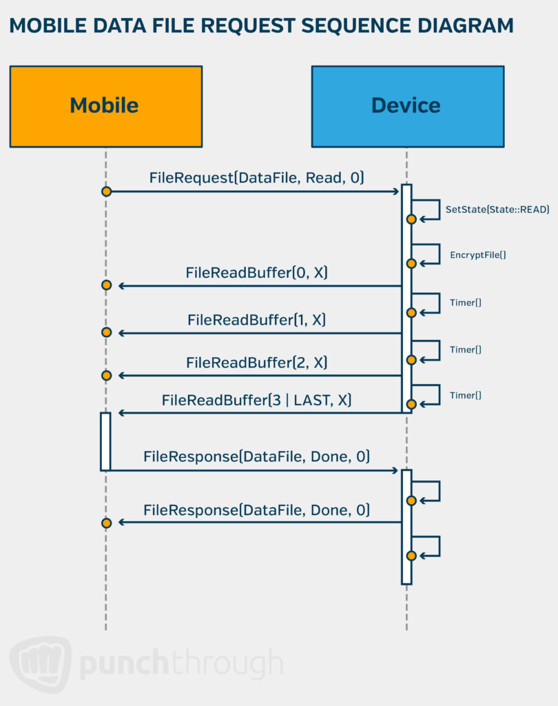
The concise yet detailed nature of these diagrams makes them invaluable for both the mobile and firmware teams, enabling them to develop a compatible file exchange interface. Without such a visual representation, conveying this information would require numerous separate requirements, making it far more complex and less efficient.
Test Interfaces
Developing test interfaces early in the design process allows teams to simulate interactions between components, reducing reliance on full-system integration for issue discovery. A well-designed debug interface can inject simulated inputs, trigger specific conditions, and replicate real-world use cases that may be difficult to reproduce manually.
This capability is particularly useful when external hardware dependencies are unavailable, allowing teams to validate firmware logic before full system integration. Investing in a rich suite of test interfaces ensures that issues are uncovered earlier and in a more controlled environment rather than surfacing unpredictably during late-stage integration.
Let’s briefly explore a typical test interface implementation for firmware development. Building a test interface requires upfront effort but pays off for developers debugging and testing new features. A serial console interface with self-documented command and response messages is the norm, as it is easy to implement, scales well, and is simple to use.
Examples of commands that may be built into this interface include:
- Manually controlling LEDs and indicators
- Injecting events into a firmware subsystem to simulate user interactions like button presses
- Triggering external events such as starting BLE pairing or receiving a message from a mock cloud endpoint
Leveraging off-the-shelf SDKs and libraries can further streamline development by providing the code needed to implement interactive consoles and abstract messaging definitions. The transport layer is typically a serial connection via a debugger or external UART, though wireless options like BLE or Wi-Fi are also viable.
However, test interfaces can introduce security risks, so they should be entirely disabled in manufacturing and production builds to prevent potential attack vectors.
Application Logging
Robust logging capabilities enable teams to monitor system events, timing, and interactions between components. Logs provide a historical record of events, making it easier to diagnose unexpected behavior and validate whether integration is proceeding as expected. Logging also helps track sequence execution, identify performance bottlenecks, and confirm whether system state transitions align with design specifications.
Application logging is supported by all major embedded SDKs and is easy to incorporate into firmware design with minimal effort. It provides an efficient way to share and compare failures, aiding debugging. Logging also lends itself well to automation, as scripts can be developed to parse and filter log messages, validate event sequences, and quickly identify errors. Regardless of project size, verbose application logging adds significant value with little setup. While the implementation is typically platform-dependent, detailed guidance can be found in the platform-specific SDKs, such as the nrf_log module for Nordic’s nRF SDK or the esp_log module for Espressif’s ESP-IDF.
Here is a snippet of a logfile from an embedded device that just completed power-up, started BLE advertising and played a ready melody. Logfile information like this is incredibly useful for troubleshooting issues and confirming expected device behavior and because of its ease of use, should be central to firmware design.
2023-12-06 08:13:48.822  [DEBUG ] device_comms.interface_serial.receiver     [33m[00:00:01.143,000] <info> StateMachine: InputManager State Change: Startup -> WaitingForButton

2023-12-06 08:13:48.867  [DEBUG ] device_comms.utils.log_parse  search_log_sequence: searching for ['StateMachine: Sys State Change: PowerUp -> Rdy']

2023-12-06 08:13:48.867  [DEBUG ] device_comms.utils.log_parse  search_log_sequence: Not all desired text was found

2023-12-06 08:13:48.972  [DEBUG ] device_comms.interface_serial.receiver     [33m[00:00:01.321,000] <info> PwrMgr: PowerMgr turned everything off[0m

2023-12-06 08:13:49.371  [DEBUG ] device_comms.interface_serial.receiver     [33m[00:00:01.720,000] <info> halAccel: INT received.[0m

2023-12-06 08:13:49.374  [DEBUG ] device_comms.utils.log_parse  search_log_sequence: searching for ['StateMachine: Sys State Change: PowerUp -> Rdy']

2023-12-06 08:13:49.374  [DEBUG ] device_comms.utils.log_parse  search_log_sequence: Not all desired text was found

2023-12-06 08:13:49.849  [DEBUG ] device_comms.interface_serial.receiver     [33m[00:00:02.213,000] <info> svcBle: StartAdv whitelist=1[0m

2023-12-06 08:13:49.865  [DEBUG ] device_comms.interface_serial.receiver     [33m[00:00:02.213,000] <info> svcBle: Advertising not started[0m

2023-12-06 08:13:49.865  [DEBUG ] device_comms.interface_serial.receiver     [33m[00:00:02.213,000] <info> StateMachine: Sys State Change: PowerUp -> Rdy[0m

2023-12-06 08:13:49.880  [DEBUG ] device_comms.utils.log_parse  search_log_sequence: searching for ['StateMachine: Sys State Change: PowerUp -> Rdy']

2023-12-06 08:13:49.880  [DEBUG ] device_comms.interface_serial.receiver     [33m[00:00:02.213,000] <info> AudioSS: Playing Melody 0[0m

2023-12-06 08:13:50.348  [DEBUG ] device_comms.interface_serial.receiver     [33m[00:00:02.712,000] <info> buzzer: Playback finished[0m

2023-12-06 08:13:50.363  [DEBUG ] device_comms.interface_serial.receiver     [33m[00:00:02.712,000] <info> PwrMgr: PowerMgr turned everything off[0m

2023-12-06 08:13:51.897  [DEBUG ] device_comms.message_bridge   [31m[47mRaw request Data:

  set_ble_pairing_mode

    hdr: 00 07 d3 04 00  payload: 01 00 00 00  crc: 93 36[0m
Versioning and Build Configurations
Careful configuration management ensures that changes to firmware do not introduce breaking updates that ripple through the system. Versioning allows teams to track changes clearly and prevents mismatched firmware versions from causing unexpected failures during integration.
Effective version control also improves coordination between stakeholders, ensuring that all teams are testing and deploying against compatible software and hardware versions. Build configurations further safeguard against unintended modifications by preventing development or debug code from being included in production firmware. By maintaining rigorous control over configurations, teams can avoid integration surprises caused by inconsistencies across different firmware builds.
Let’s explore the specifics and typical ways to implement versioning and build configurations for firmware. Firmware versioning is typically implemented using an x.y.z format, with the goal of conveying information about backward compatibility, application version, and the intended deployment environment.
For example, the build version (x) might be:
- 1.y.z for development builds
- 10.y.z for manufacturing
- 100.y.z for production
Each build configuration—development, manufacturing, and production—may include or exclude specific features. Development builds typically include full testing capabilities, manufacturing builds focus on provisioning tasks and exclude unnecessary features, and production builds are “locked down” with minimal testing support to reduce size and security risks.
The minor version (z) typically indicates backward-compatible changes, while the major version (y) signifies breaking changes, such as protocol updates. Using a consistent versioning format helps align teams—so, for example, if a mobile development team receives a firmware release with a new major version (y), they would anticipate potential breaking changes and coordinate system updates accordingly. Conversely, if the update only includes a new minor version (z), the mobile team can expect no failures during integration with the previous version of their app.
State Machines, Event Frameworks
Explicitly defining system states and transitions prevents unpredictable behavior during integration. A structured state machine ensures that each component operates within a well-defined set of conditions, reducing ambiguity and unintended interactions. Without clear state definitions, systems may enter undefined modes, leading to erratic behavior or integration failures.
By enforcing strict control flow, such as allowing only valid commands in a given state, firmware can prevent invalid operations from propagating through the system. Thoughtful state management also simplifies debugging and ensures that system behavior remains consistent even under unexpected conditions.
There are several ways to implement a state machine and event framework in firmware, and one common approach in C++ involves defining abstract base classes that encapsulate event definitions and state machine logic within an RTOS thread. Each class has an RTOS queue for receiving system events, ensuring proper communication between components.
For every subsystem, such as BLE, Wi-Fi, Buttons, LEDs, or Buzzers, a separate state machine class is implemented. This modular, interface-centric approach helps organize the firmware and makes it easier to scale and extend. Once the foundation is in place, development focuses on adding logic within each subsystem to handle system events.
This method provides a thread-safe, stateful, event-driven design, which is particularly valuable in large teams, as it allows for easy addition of new features while maintaining clear separation of concerns.
Derating
The engineering concept of derating can be applied in firmware design to improve system robustness and handle unexpected design changes and scope increases. Selecting components is an early and critical design choice.
Choosing components with excess capability can prevent unexpected integration issues caused by resource limitations. Choosing hardware with more memory, I/O, or computational power than initially required provides flexibility to accommodate unforeseen design changes. For example, if a system is expected to need 2MB of memory, selecting an 8MB variant ensures headroom for future updates, additional features, or unexpected performance constraints discovered during integration. Investing in hardware with extra capacity early in the design process can prevent costly redesigns later.
Consider the example of implementing a firmware application that involves extensive JSON parsing from a cloud endpoint. Ideally, you would want to use an off-the-shelf JSON parsing library, but many of these libraries rely on memory-intensive solutions, such as C strings and dynamic memory allocation.
If your application doesn’t have enough memory to support such a library, what would normally be a quick integration can turn into a lengthy process, as you spend days or even weeks developing a memory-optimized version of what is otherwise readily available.
Secure Boot and Firmware Updates
Planning for robust firmware update mechanisms from the outset ensures that devices can recover from integration failures and security vulnerabilities. Implementing integrity checks and rollback capabilities prevents bricking devices due to failed updates. Designing firmware with an update strategy in mind enables teams to address integration issues in the field without requiring costly manual intervention.
Major semiconductor vendors typically provide SDKs that include secure boot and OTA firmware update solutions, often integrated into the default build system, making them easier to include than exclude. These capabilities have become industry standard for modern IoT products and are increasingly in demand for medical devices as well. Leveraging these built-in solutions streamlines development, ensuring devices can securely update firmware while maintaining integrity and rollback protections to prevent bricking.
Error Handling
A well-defined error-handling strategy prevents failures from cascading through the system. Implementing timeout and retry mechanisms ensures that transient errors do not cause complete system failures. Watchdogs and fallback states maintain system stability even when unexpected conditions arise.
Additionally, centralizing error reporting prevents fragmented error-handling logic, making integration and debugging more manageable. By considering edge cases, such as out-of-range sensor values or peripheral failures, teams can design systems that fail gracefully rather than unpredictably.
Many embedded SDKs include built-in error-handling mechanisms such as panic handlers and error loggers, which provide high value with minimal effort. These often come with underlying assert handlers, making them easy to leverage.
Asserts are particularly useful for enforcing expectations, catching errors early, and making root causes more apparent. Since they require little effort to implement, we use them ubiquitously to improve system robustness and debugging efficiency.
Additionally, defining a discrete error state early in development, even if initially unimplemented, encourages developers to centralize error handling, ensuring a more structured approach to fault management.
Modular and Layered Architecture
Breaking firmware into well-defined modules isolates failures and reduces unintended side effects during integration. Encapsulating features within independent modules allows errors to be contained within localized sections of the system.
Additionally, structuring firmware into distinct layers—such as application logic, service layers, hardware abstraction, and drivers—ensures that updates and changes do not inadvertently affect unrelated parts of the system. A modular design improves maintainability and simplifies integration by clearly defining boundaries between components.
A typical embedded device follows a layered architecture, including:
- The device SDK
- Soft devices
- HAL (Hardware Abstraction Layer)
- Subsystems
- Application layers
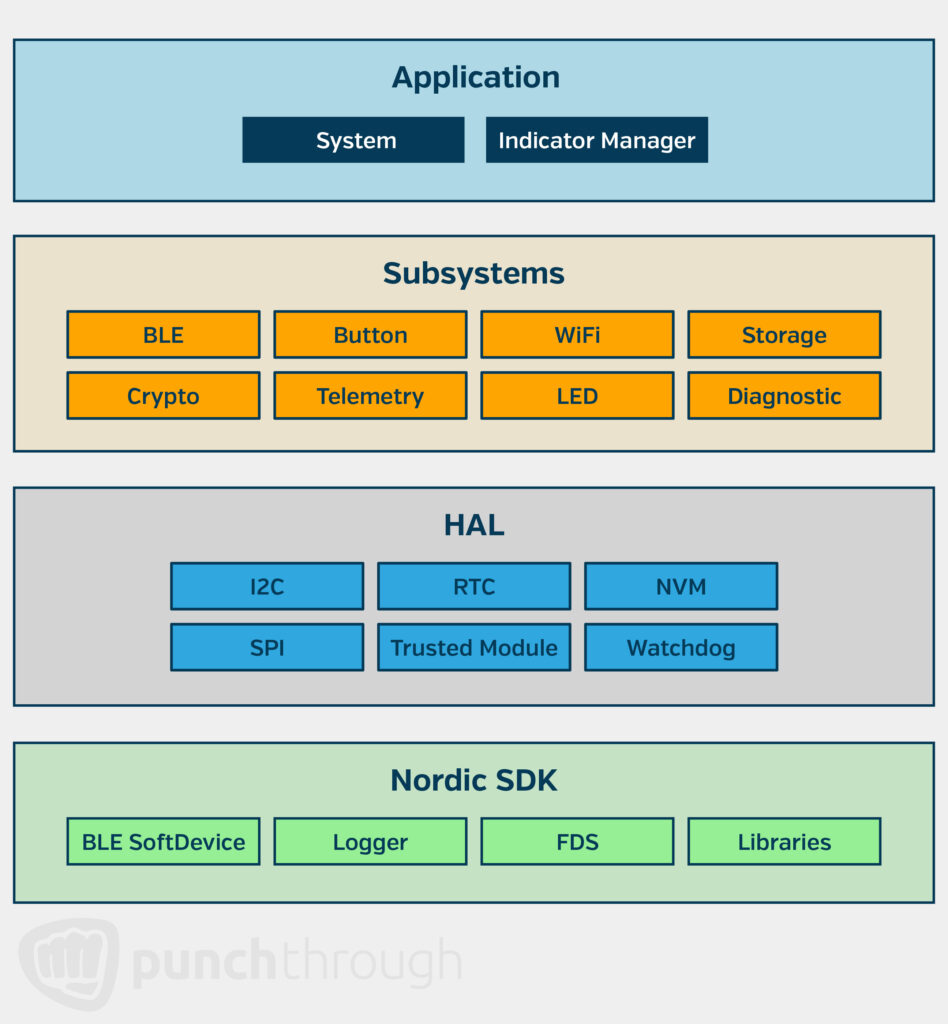
For example, in a Nordic nRF-based product with BLE, Wi-Fi, LED, and Button interfaces, most application development occurs in the top layers, while the SDK and HAL are vendor-provided.
Each subsystem can be implemented as a separate class with corresponding .cpp and .h files, making the architecture well-suited for an RTOS like Zephyr or FreeRTOS, where subsystems run as independent tasks/threads and communicate safely through an event-driven approach.
The diagram below illustrates this layered architecture, showing how different firmware components interact. A key takeaway is the use of interface-centric subsystems to encapsulate application functionality, adding structure to firmware architecture and making development more modular and scalable.
When to Bring in a Firmware Partner
Even with a strong firmware development process in place, integration challenges can arise—whether from shifting requirements, unforeseen technical constraints, or the complexity of coordinating across teams. While some organizations have the in-house expertise to manage these issues, others may find that bringing in a specialized partner helps de-risk development, accelerate timelines, and improve long-term product reliability.
Bringing in external expertise makes the most sense when:
- You’re working with new or unfamiliar technologies. A partner with deep embedded systems experience can help navigate architectural decisions, balancing performance, power consumption, and scalability.
- Integration issues are slowing down development. If your team is spending more time debugging than building, an outside perspective can help pinpoint root causes, implement best practices, and get development back on track.
- You need to ensure reliability in high-stakes environments. Products in industries like medical, industrial, and IoT must meet strict safety, regulatory, and real-world performance requirements. Experienced firmware expertise can help prevent costly late-stage failures.
- Your team is stretched thin. When internal resources are focused on core development, a firmware partner can support integration efforts, develop test strategies, and ensure seamless interaction between hardware and software components.
Whether you’re at the start of development or facing unexpected roadblocks in integration, the right expertise at the right time can prevent delays, reduce risk, and ultimately result in a better, more scalable product.
Building Resilient Firmware is the Key to Seamless Integration
Preventing device integration failures starts with proactive firmware design. While meeting basic product requirements is essential, additional considerations—such as modular architecture, standardized interfaces, and comprehensive error handling—can significantly enhance integration robustness. These early design choices help identify potential issues before they escalate, reducing costly rework and delays.
By embedding integration-focused principles into firmware development from the outset, teams can detect and resolve compatibility challenges earlier in the product lifecycle. This approach not only streamlines development but also leads to a more resilient and adaptable product, ultimately improving reliability and user experience.